Difference between revisions of "Workshop"
(→Challenges) |
m |
||
| (45 intermediate revisions by 4 users not shown) | |||
| Line 3: | Line 3: | ||
At its simplest, the power measurement shield works by sampling the voltage drop across a resistor wire inline with a power supply. It is implemented as a shield for a ST Microelectronics STM32F4 Discovery board. The STM32F4 is used to process the raw data and pass it out over USB. The shield can measure up to three external targets simultaneously, as well as measuring its own energy usage. | At its simplest, the power measurement shield works by sampling the voltage drop across a resistor wire inline with a power supply. It is implemented as a shield for a ST Microelectronics STM32F4 Discovery board. The STM32F4 is used to process the raw data and pass it out over USB. The shield can measure up to three external targets simultaneously, as well as measuring its own energy usage. | ||
| − | The hardware is a fully open design by Dr Simon Hollis of Bristol | + | The hardware is a fully open design by Dr Simon Hollis of University of Bristol. It may be downloaded from GitHub: https://github.com/mageec/powersense-shield. The software and firmware are also open source, designed by James Pallister of University of Bristol, and available at https://github/jpallister/stm32f4-energy-monitor. |
| − | + | Follow the quick start guide if you are using a MAGEEC USB stick. | |
| + | <center> | ||
| + | [[File:Energymonitor1.jpg|700px|Image of the Energy Monitor]] | ||
| + | </center> | ||
| + | |||
| + | ==Kit contents / Required materials== | ||
| + | |||
| + | The following images shows which parts you should have for this workshop. Note: the target board can be substituted for an alternative platform, perhaps a shrimping kit. | ||
| + | |||
| + | <center> | ||
| + | [[File:Kitcontents2.png|600px|Kit contents]] | ||
| + | </center> | ||
| + | |||
| + | The kit contains: | ||
| + | * A target board. This is the board that will be measured. | ||
| + | * An energy 'management' board. This board interfaces with the energy shield, converting the raw power data into energy measurements and handles communication with the PC. Note, the top of the board is mini-USB, the programming only interface. The bottom of the board is micro USB and is used for normal usage (taking energy measurements). | ||
| + | * An energy shield. This board contains the electronics and headers necessary to attach a target board for energy measurement. | ||
| + | * 6 Jumpers. These allow the resistors to be selected on the energy shield | ||
| + | * 4 wire jumpers. These are used to connect the energy shield to the target board. | ||
| + | * mini USB cable. Used for programming the firmware into the management board, and (sometimes) the target board. | ||
| + | * micro USB cable. This is used to connect with the energy management board. | ||
| + | |||
| + | ==Quick Start== | ||
| + | |||
| + | Follow this section if you have booted from the MAGEEC USB stick - it already contains all the libraries and software needed. | ||
| + | |||
| + | Connect up all the hardware as shown in the ''Connecting the hardware section''. | ||
| + | |||
| + | The first step is to put the firmware on the STM32F4DISCOVERY board. To do this plug in the STM32F4DISCOVERY board with the mini-USB cable and open a terminal (Ctrl+Alt+T) | ||
| + | |||
| + | $ cd Desktop/stlink | ||
| + | $ ./st-util | ||
| + | |||
| + | This starts the GDB server that will communicate between the debugger and the board. Now open another terminal (Ctrl+Alt+T) and start the debugger to flash the firmware to the board. | ||
| + | |||
| + | $ cd Desktop | ||
| + | $ arm-none-eabi-gdb stm32f4-energy-monitor/src/firmware/energy_monitor | ||
| + | > target extended-remote :4242 | ||
| + | > load | ||
| + | > quit # Answer "y" to quit | ||
| + | |||
| + | The ''st-util'' program in the other terminal can now be closed. | ||
| + | |||
| + | The board is now flashed, and the mini-usb cable should now be disconnected. The board can be connected via the other USB port now (micro-USB). This allows the firmware to communicate with the host. There is no direct power connection from this client USB port, so take a jumper cable and connect it from PA9 (client USB bus power) to the 5V pin, as below. | ||
| + | |||
| + | <center> | ||
| + | [[File:5vconnection.png|600px|5V connection]] | ||
| + | </center> | ||
| + | |||
| + | If you are using the MAGEEC tools USB, skip the next section. Now look at the '''Connecting a target board'' ' section. | ||
==Software Requirements== | ==Software Requirements== | ||
| − | Skip this section if you are running from the MAGEEC live CD. | + | Skip this section if you are running from the MAGEEC live CD. Download it from: |
| + | |||
| + | * jpallister.com/documents/ubuntu-mageec.iso | ||
This section sets up the packages required to compile the firmware for the energy monitor board, run the python scripts to communicate with the board and toolchain to compile for an arduino target board. | This section sets up the packages required to compile the firmware for the energy monitor board, run the python scripts to communicate with the board and toolchain to compile for an arduino target board. | ||
| Line 16: | Line 67: | ||
Install packages required to build the firmware for the energy monitor board | Install packages required to build the firmware for the energy monitor board | ||
| − | + | sudo add-apt-repository ppa:terry.guo/gcc-arm-embedded | |
| − | |||
If on Ubuntu 13.10, the following is required | If on Ubuntu 13.10, the following is required | ||
| − | + | sed -i 's/saucy/raring/' /etc/apt/sources.list.d/terry_guo-gcc-arm-embedded-saucy.list | |
| + | sudo apt-get update | ||
| + | Install an ARM toolchain | ||
| − | + | sudo apt-get install gcc-arm-none-eabi | |
| − | + | If you're using a non-ubuntu derivative, you can download the toolchain directly from launchpad. | |
| + | https://launchpad.net/gcc-arm-embedded/+download | ||
If the target board is a shrimping kit / arduino / AVR | If the target board is a shrimping kit / arduino / AVR | ||
| − | + | sudo apt-get install gcc-avr gdb-avr avr-libc avrdude arduino | |
Install other libraries needed | Install other libraries needed | ||
| − | + | sudo apt-get install git python-numpy python-scipy build-essential python-pip autoconf automake autotools-dev libtool libusb-1.0-0-dev libusb-0.1-4 python-matplotlib | |
| − | + | sudo pip install pyusb docopt | |
| + | If you receive an error installing pyusb, of the form 'Could not find a version that satisfies the requirement pyusb' then attempt the installation again with a --pre option, e.g. | ||
| + | sudo pip install --pre pyusb docopt | ||
| + | |||
The following udev rules will need to be install, to use the board without being root | The following udev rules will need to be install, to use the board without being root | ||
| − | + | https://github.com/jpallister/stm32f4-energy-monitor/blob/pyusb/53-energy-monitor.rules | |
| − | + | https://github.com/jpallister/stlink/blob/master/49-stlinkv2.rules | |
| + | |||
| + | For example using wget against the ''raw version'' from GitHub. | ||
| + | |||
| + | wget https://raw2.github.com/jpallister/stm32f4-energy-monitor/pyusb/53-energy-monitor.rules | ||
| + | wget https://raw2.github.com/jpallister/stlink/master/49-stlinkv2.rules | ||
| + | wget https://raw2.github.com/jpallister/stlink/master/49-stlinkv1.rules | ||
| + | |||
| + | and install with: | ||
| + | |||
| + | sudo cp 53-energy-monitor.rules /etc/udev/rules.d/ | ||
| + | sudo cp 49-stlinkv2.rules /etc/udev/rules.d/ | ||
| + | sudo cp 49-stlinkv1.rules /etc/udev/rules.d/ | ||
| + | sudo service udev restart | ||
==Connecting the hardware== | ==Connecting the hardware== | ||
First mount the shield as shown in the following image. There will probably be a jumper supplied with the STM32F4, which will need removing, with the pins slotting into a socket on the underside of the shield. | First mount the shield as shown in the following image. There will probably be a jumper supplied with the STM32F4, which will need removing, with the pins slotting into a socket on the underside of the shield. | ||
| + | |||
| + | The energy shield has four measurement points, input 1, 2 and 3, and a self measurement point. These are documented on the silkscreen of the board. | ||
<center> | <center> | ||
| Line 70: | Line 141: | ||
| + | To power the board without the programming cable connected, a wire should be connected from the PA9 pin to the 5V pin (see below). '''Warning: don't connect cables to both USB ports with a power cable connected'''. | ||
| − | + | <center> | |
| + | [[File:5vconnection.png|600px|5V connection]] | ||
| + | </center> | ||
==Software setup== | ==Software setup== | ||
| Line 81: | Line 155: | ||
The energy monitor firmware uses a library called libopencm3 to interface to the hardware peripherals provided by the board. This needs to be downloaded and compiled into the toolchain: | The energy monitor firmware uses a library called libopencm3 to interface to the hardware peripherals provided by the board. This needs to be downloaded and compiled into the toolchain: | ||
| − | + | $ git clone https://github.com/libopencm3/libopencm3 | |
| − | + | $ cd libopencm3 | |
| − | + | $ make | |
| − | + | $ sudo make DETECT_TOOLCHAIN=1 install | |
| − | + | $ cd .. | |
Next, we need to obtain the energy monitor sources. | Next, we need to obtain the energy monitor sources. | ||
| − | + | $ git clone https://github.com/jpallister/stm32f4-energy-monitor | |
| − | + | $ cd stm32f4-energy-monitor | |
| − | + | $ git checkout pyusb | |
Then configure and compile specifying that we want to compile ARM firmware: | Then configure and compile specifying that we want to compile ARM firmware: | ||
| − | + | $ ./configure --host=arm-none-eabi | |
| − | + | $ make | |
This will produce a file '''energy_monitor''' in src/firmware/. The next step is to flash this to the STM32F4 board. The board has two USB interfaces, one for programming and the other for the firmware's use. The programming USB interface is at the top of the board, connected with a USB mini cable. Make sure this is plugged in, and follow the steps below to flash the board. | This will produce a file '''energy_monitor''' in src/firmware/. The next step is to flash this to the STM32F4 board. The board has two USB interfaces, one for programming and the other for the firmware's use. The programming USB interface is at the top of the board, connected with a USB mini cable. Make sure this is plugged in, and follow the steps below to flash the board. | ||
| Line 104: | Line 178: | ||
To communicate with the board, we need a gdb server to enable communication between the debugger, GDB, and the target board. This is provided by the opensource st-link utility. | To communicate with the board, we need a gdb server to enable communication between the debugger, GDB, and the target board. This is provided by the opensource st-link utility. | ||
| − | + | $ cd .. | |
| − | + | $ git clone https://github.com/jpallister/stlink | |
| − | + | $ cd stlink | |
| − | + | $ ./autogen.sh | |
| − | + | $ ./configure | |
| − | + | $ make | |
Now, we need to run this program and leave it running in - it will talk to GDB and the STM32F4 in the background. | Now, we need to run this program and leave it running in - it will talk to GDB and the STM32F4 in the background. | ||
| − | + | $ ./st-util | |
In a new terminal, we can now flash the firmware to the board: | In a new terminal, we can now flash the firmware to the board: | ||
| − | + | $ arm-none-eabi-gdb | |
Choose the firmware file, tell GDB to talk to the GDB server (st-util) on port 4242 and load the firmware onto the board. | Choose the firmware file, tell GDB to talk to the GDB server (st-util) on port 4242 and load the firmware onto the board. | ||
| − | + | (gdb) file stm32f4-energy-monitor/src/firmware/energy_monitor | |
| − | + | (gdb) target extended-remote :4242 | |
| − | + | (gdb) load | |
| + | (gdb) detach | ||
| + | (gdb) quit | ||
| + | |||
| + | '''Note.''' The ''load'' command does not always work first time. If you get an error message, just repeat the ''load'' command. | ||
| + | At this point kill st-utils and reset the STM4 board by pressing the black button. | ||
Congratulations. You now have a programmed energy monitor board. At this point, you can disconnect the mini-USB programming cable. The micro-USB cable can now be connected to the board, and you should have a fully functioning energy monitor. | Congratulations. You now have a programmed energy monitor board. At this point, you can disconnect the mini-USB programming cable. The micro-USB cable can now be connected to the board, and you should have a fully functioning energy monitor. | ||
| − | == | + | ==Connecting a target board== |
| + | |||
| + | [[File:Stm32vldiscovery2.png|thumbnail]] | ||
| + | |||
| + | This section discusses how to connect target boards to the energy measurement. Most of the time it makes most sense to connect to the energy shield's ''input 1''. | ||
| + | |||
| + | The energy measurement board works by inserting a small resistor between the positive power rail and the processors to be measured. | ||
| − | A python library is provided which communicates with the USB board, and transfers the energy data back. | + | ===STM32VLDISCOVERY=== |
| + | |||
| + | This section discusses how to connect a Cortex-M3 STM32VLDISCOVERY board (pictured right). You will need 3 jumper cables to connect the target board to the energy measurement board. | ||
| + | |||
| + | Locate the '''idd''' jumper next to the larger chip on the board and remove it. This is a jumper which allows the power supply to the chip to be intercepted. The following connections need to be made: | ||
| + | * '''OUT''' pin of the measurement shield to the side of the '''idd''' header closest to the chip. | ||
| + | * '''IN''' pin of the measurement shield to the side of the '''idd''' header furthest from the chip. | ||
| + | * '''GND''' pin of the measurement shield to a ground pin on the target board. | ||
| + | |||
| + | Connect this board to the computer with the USB-mini cable. | ||
| + | |||
| + | ===AVR/Shrimping kit=== | ||
| + | |||
| + | [[File:Shrimping.png|thumbnail]] | ||
| + | |||
| + | The following connections should be made: | ||
| + | *The '''IN''' pin of the measurement board should be connected to the voltage into the breadboard. | ||
| + | *The '''OUT''' pin of the measurement board should go back to the breakboard, and into the power supply of the chip | ||
| + | *The '''GND''' pin on the measurement board should be plugged into one of the ground pins of the chip. | ||
| + | |||
| + | ==Using the energy measurement software== | ||
| + | |||
| + | A python library is provided which communicates with the USB board, and transfers the energy data back. Several example scripts are provided. | ||
The first script, read.py, sets up a port to trigger the energy measurement (PA0, the blue button). Pressing the button down causes the board to start measuring. Releasing the button causes the board to stop measuring and the data to be transferred back. | The first script, read.py, sets up a port to trigger the energy measurement (PA0, the blue button). Pressing the button down causes the board to start measuring. Releasing the button causes the board to stop measuring and the data to be transferred back. | ||
| Line 138: | Line 245: | ||
> cd stm32f4-energy-monitor/src/python/ | > cd stm32f4-energy-monitor/src/python/ | ||
> python read.py | > python read.py | ||
| + | # Press the blue button on the energy management board | ||
| + | # Ctrl+C to exit | ||
The second script, continuous.py, starts measurement point 1, then repeatedly gets the current measurement. This will allow you to see the energy consumed since this beginning of the script. | The second script, continuous.py, starts measurement point 1, then repeatedly gets the current measurement. This will allow you to see the energy consumed since this beginning of the script. | ||
> python continuous.py | > python continuous.py | ||
| + | # Ctrl+C to exit | ||
| + | |||
| + | There is one more script, which allows you to see the instantaneous current and voltage values at a particular measurement point. The measurement points to be used are specified on the command line. | ||
| + | |||
| + | > python debug.py 1 3 | ||
| + | # Ctrl+C to exit | ||
| + | |||
| + | A further script plots the instantaneous current, voltage and power on a graph. Selecting the checkboxes allows the values from different measurement points to be displayed. The frequency and type of graphs displayed can also be changed. | ||
| + | > python interactive_graph.py | ||
| + | |||
| + | This last script is particularly useful if left open in the background. | ||
| + | |||
| + | ==Stuff to do with the STM32VLDISCOVERY board== | ||
| + | |||
| + | A repository has been included with some examples of what can be done with the energy measurement kit. There are 4 examples: | ||
| + | * fancyblink. This flashes the two LEDs at different times, allowing the energy consumption of different types of LED to be seen. | ||
| + | * sleep. This program puts the processor to sleep until a button is pressed, and then it does some computation. | ||
| + | * deepsleep. Similar to above, except this program enables the deep sleep mode, reducing energy consumption even more. | ||
| + | * deepsleepclk. This program is the same as deepsleep, but changes the clock after doing some of the computation. | ||
| + | |||
| + | The following commands can be used to compile and flash the board. We need to start the st-util GDB server again, this time to talk to the STM32VLDISCOVERY board. | ||
| + | |||
| + | $ cd stlink | ||
| + | $ ./st-util -1 | ||
| + | |||
| + | In another terminal, we can compile and flash the programs | ||
| + | |||
| + | $ cd energy-examples/fancyblink | ||
| + | $ make | ||
| + | $ arm-none-eabi-gdb fancyblink.elf | ||
| + | > target extended-remote :4242 | ||
| + | > load | ||
| + | # NOTE: sometimes the flashing fails. If this happens, press the reset (black) button and try 'load' again. If it still doesn't work, follow the steps below. | ||
| + | > continue | ||
| + | |||
| + | The program will now be running. The energy can be seen by running any of the programs listed in the previous section - the graph provides a nice way to visualise this. | ||
| + | |||
| + | ===Failed to flash=== | ||
| + | |||
| + | There is an odd bug where sometimes the STM32VLDISCOVERY won't flash. This can be fixed by the following steps: | ||
| + | |||
| + | Plug the STM32VLDISCOVERY in while holding down the black reset button. Then run the following command (after releasing the button) | ||
| − | + | $ stlink/st-flash erase | |
| − | + | This should erase all of the device. The above steps for flashing a program to the device can then be attempted again. | |
==Challenges== | ==Challenges== | ||
| − | This section gives some examples for you to try out with the energy measurement kit. | + | This section gives some other examples for you to try out with the energy measurement kit. |
===Persistence of Vision=== | ===Persistence of Vision=== | ||
| Line 164: | Line 315: | ||
* Does an interrupt driven version of the code run more efficiently? | * Does an interrupt driven version of the code run more efficiently? | ||
| − | ==Blinking, ADCs, Peripherals and more== | + | ===Blinking, ADCs, Peripherals and more=== |
The libopencm3-examples repository has many different programs demonstrating what the STM32F boards can do. Instrument some of these examples with energy measurement, for example: | The libopencm3-examples repository has many different programs demonstrating what the STM32F boards can do. Instrument some of these examples with energy measurement, for example: | ||
Latest revision as of 10:49, 20 May 2015
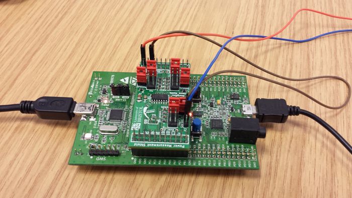
The MAGEEC project has designed a board for high frequency measurement of energy usage. This workshop will guide you through setting up and using the MAGEEC energy measurement boards.
At its simplest, the power measurement shield works by sampling the voltage drop across a resistor wire inline with a power supply. It is implemented as a shield for a ST Microelectronics STM32F4 Discovery board. The STM32F4 is used to process the raw data and pass it out over USB. The shield can measure up to three external targets simultaneously, as well as measuring its own energy usage.
The hardware is a fully open design by Dr Simon Hollis of University of Bristol. It may be downloaded from GitHub: https://github.com/mageec/powersense-shield. The software and firmware are also open source, designed by James Pallister of University of Bristol, and available at https://github/jpallister/stm32f4-energy-monitor.
Follow the quick start guide if you are using a MAGEEC USB stick.
Contents
Kit contents / Required materials
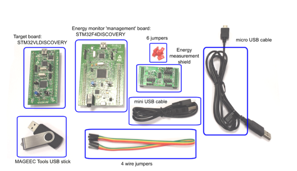
The following images shows which parts you should have for this workshop. Note: the target board can be substituted for an alternative platform, perhaps a shrimping kit.
The kit contains:
- A target board. This is the board that will be measured.
- An energy 'management' board. This board interfaces with the energy shield, converting the raw power data into energy measurements and handles communication with the PC. Note, the top of the board is mini-USB, the programming only interface. The bottom of the board is micro USB and is used for normal usage (taking energy measurements).
- An energy shield. This board contains the electronics and headers necessary to attach a target board for energy measurement.
- 6 Jumpers. These allow the resistors to be selected on the energy shield
- 4 wire jumpers. These are used to connect the energy shield to the target board.
- mini USB cable. Used for programming the firmware into the management board, and (sometimes) the target board.
- micro USB cable. This is used to connect with the energy management board.
Quick Start
Follow this section if you have booted from the MAGEEC USB stick - it already contains all the libraries and software needed.
Connect up all the hardware as shown in the Connecting the hardware section.
The first step is to put the firmware on the STM32F4DISCOVERY board. To do this plug in the STM32F4DISCOVERY board with the mini-USB cable and open a terminal (Ctrl+Alt+T)
$ cd Desktop/stlink
$ ./st-util
This starts the GDB server that will communicate between the debugger and the board. Now open another terminal (Ctrl+Alt+T) and start the debugger to flash the firmware to the board.
$ cd Desktop
$ arm-none-eabi-gdb stm32f4-energy-monitor/src/firmware/energy_monitor
> target extended-remote :4242
> load
> quit # Answer "y" to quit
The st-util program in the other terminal can now be closed.
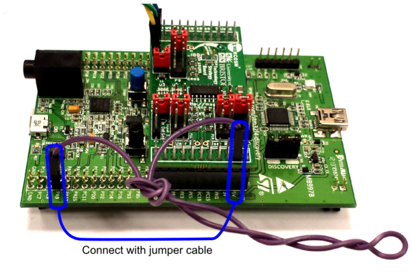
The board is now flashed, and the mini-usb cable should now be disconnected. The board can be connected via the other USB port now (micro-USB). This allows the firmware to communicate with the host. There is no direct power connection from this client USB port, so take a jumper cable and connect it from PA9 (client USB bus power) to the 5V pin, as below.
If you are using the MAGEEC tools USB, skip the next section. Now look at the 'Connecting a target board ' section.
Software Requirements
Skip this section if you are running from the MAGEEC live CD. Download it from:
- jpallister.com/documents/ubuntu-mageec.iso
This section sets up the packages required to compile the firmware for the energy monitor board, run the python scripts to communicate with the board and toolchain to compile for an arduino target board.
Install packages required to build the firmware for the energy monitor board
sudo add-apt-repository ppa:terry.guo/gcc-arm-embedded
If on Ubuntu 13.10, the following is required
sed -i 's/saucy/raring/' /etc/apt/sources.list.d/terry_guo-gcc-arm-embedded-saucy.list
sudo apt-get update
Install an ARM toolchain
sudo apt-get install gcc-arm-none-eabi
If you're using a non-ubuntu derivative, you can download the toolchain directly from launchpad.
https://launchpad.net/gcc-arm-embedded/+download
If the target board is a shrimping kit / arduino / AVR
sudo apt-get install gcc-avr gdb-avr avr-libc avrdude arduino
Install other libraries needed
sudo apt-get install git python-numpy python-scipy build-essential python-pip autoconf automake autotools-dev libtool libusb-1.0-0-dev libusb-0.1-4 python-matplotlib
sudo pip install pyusb docopt
If you receive an error installing pyusb, of the form 'Could not find a version that satisfies the requirement pyusb' then attempt the installation again with a --pre option, e.g.
sudo pip install --pre pyusb docopt
The following udev rules will need to be install, to use the board without being root
https://github.com/jpallister/stm32f4-energy-monitor/blob/pyusb/53-energy-monitor.rules
https://github.com/jpallister/stlink/blob/master/49-stlinkv2.rules
For example using wget against the raw version from GitHub.
wget https://raw2.github.com/jpallister/stm32f4-energy-monitor/pyusb/53-energy-monitor.rules
wget https://raw2.github.com/jpallister/stlink/master/49-stlinkv2.rules
wget https://raw2.github.com/jpallister/stlink/master/49-stlinkv1.rules
and install with:
sudo cp 53-energy-monitor.rules /etc/udev/rules.d/
sudo cp 49-stlinkv2.rules /etc/udev/rules.d/
sudo cp 49-stlinkv1.rules /etc/udev/rules.d/
sudo service udev restart
Connecting the hardware
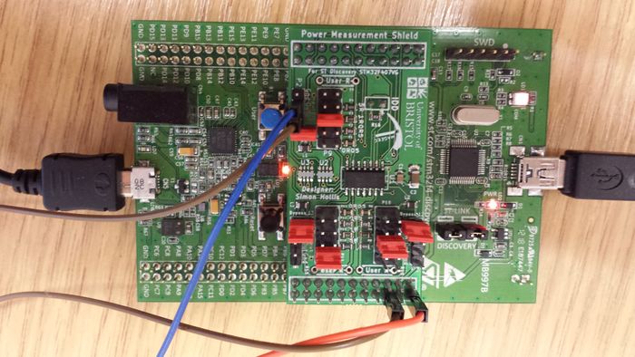
First mount the shield as shown in the following image. There will probably be a jumper supplied with the STM32F4, which will need removing, with the pins slotting into a socket on the underside of the shield.
The energy shield has four measurement points, input 1, 2 and 3, and a self measurement point. These are documented on the silkscreen of the board.
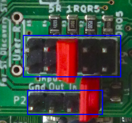
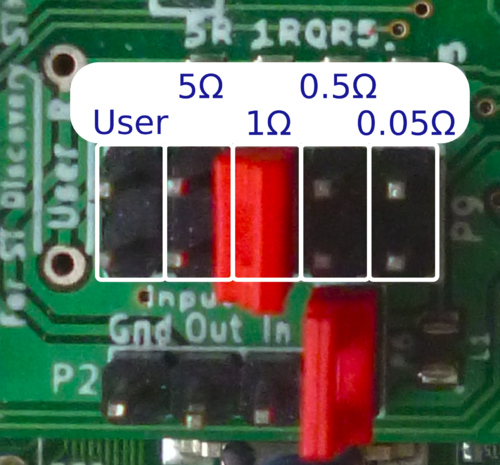
For each measurement point there are two headers. One 4x1 offering pins labelled GND, OUT and IN (more on the 4th one later) and one 5x2 for selecting an inline resistor (see below).
The target power supply should be intercepted, and wired to the IN pin, with the OUT pin then connected to the power supply on the target board. GND should be connected to ground on the target board. Power supplies up to 5V are supported. Although the voltage drop is sufficient to give the current measurement, a GND connection (not shown in the above picture) is needed to get an absolute voltage measurement.
The 4th pin next to IN is a jumper to bypass an inductor. Sometimes the only way to intercept the power supply on a target board is to cut out the inductor. In this case, remove the jumper to use the inductor on the shield instead. The target device can be powered from the shield if desired. In this case IN should be connected to the 3.3V or 5V supply on the shield (the above shows this, with the brown wire picking up the 3.3V supply). A maximum of 100mA draw is available in total.
The choice of resistor depends on the target maximum power consumption. Values of 0.05Ω, 0.5Ω, 1Ω and 5Ω are provided (the 5th slot is unused and can be used to supply your own resistor). The objective is a maximum 50mV drop.
To power the board without the programming cable connected, a wire should be connected from the PA9 pin to the 5V pin (see below). Warning: don't connect cables to both USB ports with a power cable connected.
Software setup
The first thing to do is to flash the STM32F4DISCOVERY board with the firmware required to take energy measurements. This firmware sets up the ADCs, USB and other peripherals, so that the board can talk to the host machine via USB. It performs the accumulation and conversion of the analog energy values coming from the power measurement shield.
In the following steps, skip any git clone commands if you are using the MAGEEC tools environment - all of the files are already provided on the desktop.
The energy monitor firmware uses a library called libopencm3 to interface to the hardware peripherals provided by the board. This needs to be downloaded and compiled into the toolchain:
$ git clone https://github.com/libopencm3/libopencm3
$ cd libopencm3
$ make
$ sudo make DETECT_TOOLCHAIN=1 install
$ cd ..
Next, we need to obtain the energy monitor sources.
$ git clone https://github.com/jpallister/stm32f4-energy-monitor
$ cd stm32f4-energy-monitor
$ git checkout pyusb
Then configure and compile specifying that we want to compile ARM firmware:
$ ./configure --host=arm-none-eabi
$ make
This will produce a file energy_monitor in src/firmware/. The next step is to flash this to the STM32F4 board. The board has two USB interfaces, one for programming and the other for the firmware's use. The programming USB interface is at the top of the board, connected with a USB mini cable. Make sure this is plugged in, and follow the steps below to flash the board.
To communicate with the board, we need a gdb server to enable communication between the debugger, GDB, and the target board. This is provided by the opensource st-link utility.
$ cd ..
$ git clone https://github.com/jpallister/stlink
$ cd stlink
$ ./autogen.sh
$ ./configure
$ make
Now, we need to run this program and leave it running in - it will talk to GDB and the STM32F4 in the background.
$ ./st-util
In a new terminal, we can now flash the firmware to the board:
$ arm-none-eabi-gdb
Choose the firmware file, tell GDB to talk to the GDB server (st-util) on port 4242 and load the firmware onto the board.
(gdb) file stm32f4-energy-monitor/src/firmware/energy_monitor
(gdb) target extended-remote :4242
(gdb) load
(gdb) detach
(gdb) quit
Note. The load command does not always work first time. If you get an error message, just repeat the load command.
At this point kill st-utils and reset the STM4 board by pressing the black button.
Congratulations. You now have a programmed energy monitor board. At this point, you can disconnect the mini-USB programming cable. The micro-USB cable can now be connected to the board, and you should have a fully functioning energy monitor.
Connecting a target board
This section discusses how to connect target boards to the energy measurement. Most of the time it makes most sense to connect to the energy shield's input 1.
The energy measurement board works by inserting a small resistor between the positive power rail and the processors to be measured.
STM32VLDISCOVERY
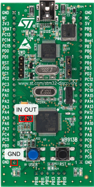
This section discusses how to connect a Cortex-M3 STM32VLDISCOVERY board (pictured right). You will need 3 jumper cables to connect the target board to the energy measurement board.
Locate the idd jumper next to the larger chip on the board and remove it. This is a jumper which allows the power supply to the chip to be intercepted. The following connections need to be made:
- OUT pin of the measurement shield to the side of the idd header closest to the chip.
- IN pin of the measurement shield to the side of the idd header furthest from the chip.
- GND pin of the measurement shield to a ground pin on the target board.
Connect this board to the computer with the USB-mini cable.
AVR/Shrimping kit
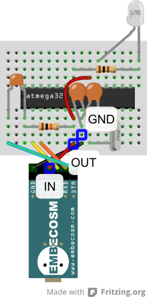
The following connections should be made:
- The IN pin of the measurement board should be connected to the voltage into the breadboard.
- The OUT pin of the measurement board should go back to the breakboard, and into the power supply of the chip
- The GND pin on the measurement board should be plugged into one of the ground pins of the chip.
Using the energy measurement software
A python library is provided which communicates with the USB board, and transfers the energy data back. Several example scripts are provided.
The first script, read.py, sets up a port to trigger the energy measurement (PA0, the blue button). Pressing the button down causes the board to start measuring. Releasing the button causes the board to stop measuring and the data to be transferred back.
   > cd stm32f4-energy-monitor/src/python/
   > python read.py
   # Press the blue button on the energy management board
   # Ctrl+C to exit
The second script, continuous.py, starts measurement point 1, then repeatedly gets the current measurement. This will allow you to see the energy consumed since this beginning of the script.
   > python continuous.py
   # Ctrl+C to exit
There is one more script, which allows you to see the instantaneous current and voltage values at a particular measurement point. The measurement points to be used are specified on the command line.
   > python debug.py 1 3
   # Ctrl+C to exit
A further script plots the instantaneous current, voltage and power on a graph. Selecting the checkboxes allows the values from different measurement points to be displayed. The frequency and type of graphs displayed can also be changed.
> python interactive_graph.py
This last script is particularly useful if left open in the background.
Stuff to do with the STM32VLDISCOVERY board
A repository has been included with some examples of what can be done with the energy measurement kit. There are 4 examples:
- fancyblink. This flashes the two LEDs at different times, allowing the energy consumption of different types of LED to be seen.
- sleep. This program puts the processor to sleep until a button is pressed, and then it does some computation.
- deepsleep. Similar to above, except this program enables the deep sleep mode, reducing energy consumption even more.
- deepsleepclk. This program is the same as deepsleep, but changes the clock after doing some of the computation.
The following commands can be used to compile and flash the board. We need to start the st-util GDB server again, this time to talk to the STM32VLDISCOVERY board.
$ cd stlink
$ ./st-util -1
In another terminal, we can compile and flash the programs
$ cd energy-examples/fancyblink
$ make
$ arm-none-eabi-gdb fancyblink.elf
> target extended-remote :4242
> load
# NOTE: sometimes the flashing fails. If this happens, press the reset (black) button and try 'load' again. If it still doesn't work, follow the steps below.
> continue
The program will now be running. The energy can be seen by running any of the programs listed in the previous section - the graph provides a nice way to visualise this.
Failed to flash
There is an odd bug where sometimes the STM32VLDISCOVERY won't flash. This can be fixed by the following steps:
Plug the STM32VLDISCOVERY in while holding down the black reset button. Then run the following command (after releasing the button)
$ stlink/st-flash erase
This should erase all of the device. The above steps for flashing a program to the device can then be attempted again.
Challenges
This section gives some other examples for you to try out with the energy measurement kit.
Persistence of Vision
This uses one of the shrimping.it persistence of vision kits. Use the following two links to build one of the kits.
Once you have built the kit, there are a few interesting things you can try
- Do different messages affect how much energy is consumed?
- Does compiling for space (-Os) make the code take less energy?
- Does an interrupt driven version of the code run more efficiently?
Blinking, ADCs, Peripherals and more
The libopencm3-examples repository has many different programs demonstrating what the STM32F boards can do. Instrument some of these examples with energy measurement, for example:
- How much power does the serial UART take for different STM32F boards?
- Use some of the interrupts to explore event driven programming - can this result in lower energy?
- Is it more energy efficient to use the built in CRC calculation, or do it in software?
Sorting
Try different sorting algorithms. Which is most energy efficient?
BEEBS
We use the a benchmark suite called BEEBS for our research. Try running some of these benchmarks on different hardware targets, with different clock speeds. Which takes the least energy?
Troubleshooting and bugs
- Check the blue light on the board. If this is lit, then an error has occurred and the board needs to be unplugged and then plugged back in. This happens if the host polls the board too frequently.
